In the previous three articles, we did a short introduction on what VFDs are, we discussed Scalar Control and 87 Hz characteristic, so this time we will take a look into Vector Control.
What is Vector Control? It isn’t something better or worse. For sure it is a more sophisticated and more expensive solution, but again – it all depends on your application. Vector Control is just another tool in your motion control toolbox. As You already know, Scalar Control is a good solution for controlling the speed of loads such as fans or pumps. That’s not all loads we might have onboard, right? Moreover, the offshore industry is full of highly demanding applications, where Scalar Control might be just not enough. Firstly, we will look at FOC and DTC algorithms. I the next articles we should take a look into other control algorithms

Principles of Vector Control
DC Drives principles
To understand the principles of Vector Control we need to go back to the principles of the DC drives.
In a DC motor, the current passing through the field winding in the stator is creating the magnetic field. Armature-brush assembly ensures this field is always at right angles to the armature winding field regardless of the rotor position. This helps us generate the maximum torque. We call it field orientation.
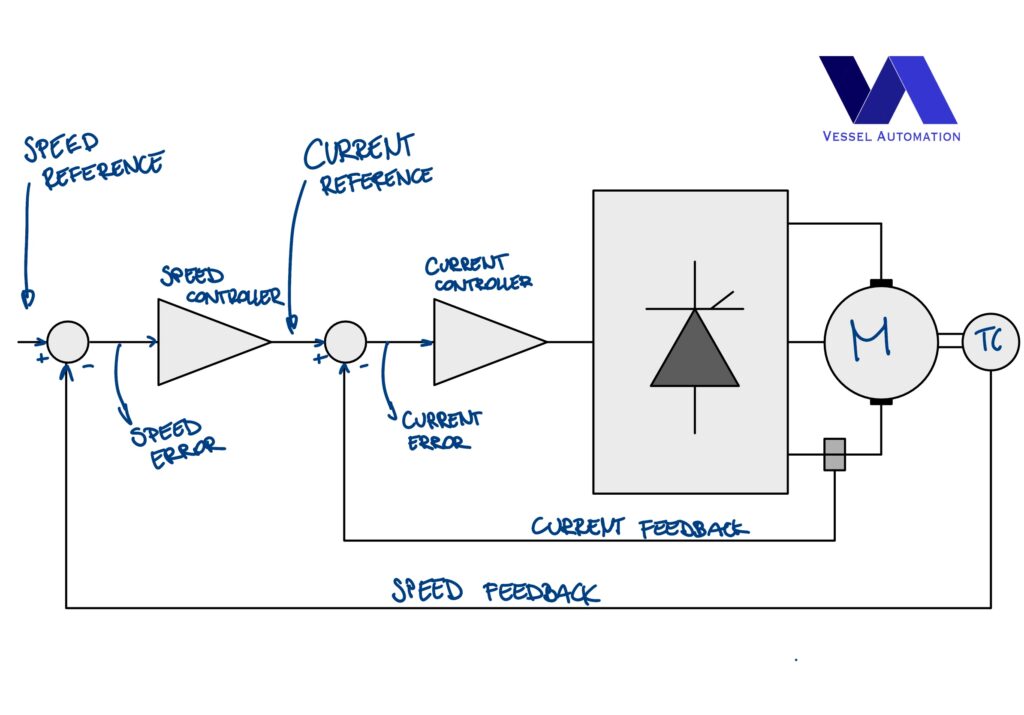
Once the field orientation is achieved, the DC motor’s torque is easily controlled by varying the armature current and by keeping the magnetizing current constant. The advantage of DC drives are that speed and torque are controlled directly through armature current. The figure below is showing the cascaded controller of the torque (inner loop) and the speed (outer loop).

DC Drives operation
In this arrangement, speed feedback is provided by a DC tachogenerator installed on the motor shaft. The feedback signal is fed to the speed controller together with the speed reference signal. The error produced this way is amplified and serves for the current (torque) controller as the current reference signal. If the speed is lower than the desired speed, the speed controller will demand current, in proportion to the error. As result, the motor speed will accelerate until it will minimalize the error.
Increase of load results in immediate deceleration and an increase of speed error. This is calling the current controller for more current and thus decrease of a speed error. Increased current causes acceleration and reduce the speed error until it will reach equilibrium. This will happen at the point, where the current that gives a torque is equal and opposite to the load torque.
For the applications requiring operation with specified torque regardless the speed, we can omit the outer speed loop. We can feed the torque signal directly to the current reference, as the current is proportional to torque. In this mode, the current remains constant at the set value, and the load determines the steady running speed.
Vector Control: Field Oriented Control
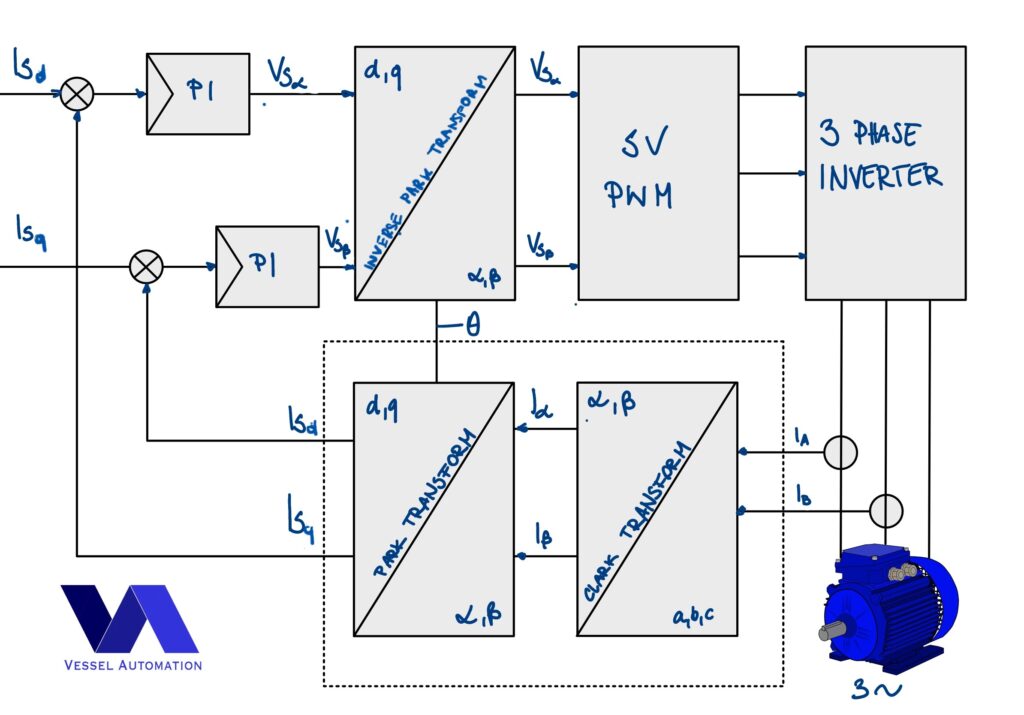
Field Oriented Control (FOC) is a form of vector control which is emulating operating conditions of a DC motor. FOC transforms all controlled variables to DC instead of AC via mathematical transformation and the goal is to control torque and flux independently. It requires knowledge of the rotor flux position and motors mathematical model. It aims to recreate the orthogonal relationship between stator and rotor fields in AC motor. There are three FOC methods:
- Direct FOC: Rotor flux angle is directly computed from flux estimation or measurement.
- Indirect FOC: Rotor flux angle is indirectly computed from available speed and slip computation.
- Sensorless FOC: Rotor flux angle is computed from position and speed estimation.
FOC operation
All three methods regardless of using the sensors for feedback or not are sharing the same working principle:

Clarke Transformation: It modifies a three-phase system to a two co-ordinate system. The Ia and Ib are components of the orthogonal reference plane and Io is the homoplanar component which is of little significance.

Park Transformation: It converts two-phase stationary system vectors to rotating system vectors. The two phases α, β frame representation calculated with the Clarke transform is then fed to a vector rotation block, where it is rotated over an angle θ to follow the d, q frame attached to the rotor flux.

So basically, what Clark-Park transformation does, it changes two-phase (third phase is not necessary) stator current vectors into torque and field currents vectors rotating at rotors speed. Inversed Park transformation transforms those vectors after PI regulation back into to two-axis orthogonal stationary reference which is a signal for Space Vector PWM block switching on and off adequate transistors.
The electronic controller of a flux-vector drive creates voltage current and frequency, and feeds these through a modulator to the AC induction motor. therefore is controlled indirectly.
FOC pros and cons
Advantages of FOC algorithm are:
- Good torque response,
- More control over motor transients,
- Full torque at zero speed, which make it a way to go when starting many heavy applications or operating drive on very low speeds,
- Performance similar to the DC drives,
Apart of that FOC presents two main disadvantages:
Vector Control: Direct Torque Control
Direct Torque Control (DTC) was developed by ABB basing on Blaschke and Depenbrock publications from 1971 and 1985, which leads to patent the solution in mid-1980s and present its first DTC AC drive to the market in 1995.

The measured input values to the DTC control are motor current and voltage. Therefore, DC-bus voltage and inverter switch positions define the motor voltage. The voltage and current signals are inputs to an accurate motor model which produces an exact actual value of stator flux and torque every 25 microseconds. Motor torque and flux comparators compare the actual values to the reference values produced by torque and flux reference controllers. The outputs from these two-level controllers update every 25 microseconds and they indicate whether the torque or flux has to be varied. Depending on the outputs from the two-level controllers, the switching logic directly determines the optimum inverter switch positions. The inverter switch positions again determine the motor voltage and current, which in turn influence the motor torque and flux.
You can find good DTC overview at:
- DTC: A motor control technique for all seasons
- ABB drives, Technical guide No. 1 Direct torque control.
DTC pros and cons
In short, the advantages of DTC are:
- DTC can by equally used with Permanent Magnet Synchronous Motors (PMSM) and Synchronous Reluctance Motors (SynRM) serving as a bridge between nowadays and future Motion Control,
- Accurate speed and torque control down to zero speed,
- Full startup torque down to zero speed,
- Fast torque response approaching physical motor limits,
- Overall better performance in comparison to scalar and FOC algorithms,
Disadvantages of DTC are again:
- Higher cost in comparison to the scalar algorithm
- More difficult commissioning process
Vector Control summary
In conclusion, to summarize all the information let’s compare previously mentioned Scalar Control and what we know about Vector Control so far.
| Scalar (U/f) | FOC | DTC | |
| Cost | Low | High | High |
| Application | Non-demanding applications, Variable torque applications, | High dynamic applications, Constant torques application, Heavy-start applications | High dynamic applications, Constant torque applications, Heavy-start applications |
| Algorithm complexity | Simple U/f control | High complexity, based on motor mathematical model | High complexity, based on motor mathematical model |
| Torque response | Low torque on low frequencies | Full torque on almost all speed range | Full torque down even to zero speed |
| Speed and torque control | Speed only | Excellent precision of speed and torque | Superior precision of speed and torque |
| Ability to control few motor by one VFD | Multi Motor Control | Controlling 1 motor at the time | Controlling 1 motor at the time |
| Commissioning | Easy | Requiring experience and more time | Requiring experience and more time |
| Performance | Good | Better | The best |
In conclusion, what are You thinking about Vector Control and what is Your experience with it? Did You encounter some challenges or was your implementation smooth as butter? In other words, let us know in the comments and stay tuned for the next articles!

[…] process You will control, You need stable torque or You need to use a scalar mode? Or maybe vector mode will fulfill your needs? Find out the correct device with available settings for the physical […]